on
ShopBot calculator
Introduction
In order to get my hand into CNC milling with the shopbot, I’ve decided to create a documentation and few tool about the good ways of CNC Milling. We have two milling machine in the Waag Fablab. But this post will only focus on the Shopbot CNC. This machine is suppose to be fast in cutting big things. But we may use it aslo so make small things. We have to figure out how precise it can be.

QuickStart
In order to use the shopbot we don’t need a lot of theory since it is an easy to use machine. But to make it do complicated things we are better to use a bit of theory.
Milling theory
Milling is about cutting material using an harder material. And this require a bit of mechanical engineering. When the flute of an end mill go trough the material we want to mill. It is using kinetic energy to tear of bit of material. This kinetic energy will be mainly transform in heat. This heat may melt material or colored them into black. It may also damage the end mill or event the machine. Milling machine are use a substrative method to bring nueric part to the physical world.
Basically milling is the cutting operation that remove metal or wood by feeding the work against a rotationg cutter having single or multiple cutting edges called “flutes”. We can use milling machine to drill, slotting, making flat or curved surface. We can even produce gear !
There are the parameters we can work on :
- The Material
- The tool
- Spindle speed (rotating speed)
- Feed rate (linear speed)
- The milling strategy
First of all with have to select the material. Depending of your project and your needs you may choose between those mmaterial with the shopbot :
- Soft wood (PlyWood)
- Hardwood (Oak)
- MDF
- PVC Foam
- PMMA, PET, POM
- Aluminium
- Brass, Copper, Bronze
- Soft steel
You may think about the mechanical performance of your material. But you can use plastic foam to make some test before getting into an expensive material. It may be good to detect error and see if the result match your needs.
When you’re done. We have to choose the right tool. Toolss are plenty and have a lot of parameters that we can play with.
Choose your tool wisely
Here is an array to choose the right tool :

Before getting into calculus you may need a bit of terminology. Here is the anatomy of an endmill :

While choosing the right mill you may think about the number of flutes. The more you have teeth the faster you can travel while cutting and so the faster the job will be. But more speed may also cause more vibration than can affect your cnc durability and also the quality of the surface. On a large scale CNC as the shopbot vibration may affect the quality when sculpting precise parts.
You may also check the max speeds of the shopbot. It is not neccessary to buy an 6 flutes if your machine can’t travel fast enough.
The max speed of the shopbot spindle is 24.000 RPM and the recomended speed is 18.000 RPM We will see how to calculate the speed and feeds further in this post…

The end mill can also be composed of different material and may be coated as well. A coated endmill will probably last longer than other depending of your usage. But they may be more expensive.
Materials :
-
High Speed Steel (HSS) provides good wear resistance and costs less than cobalt or carbide end mills. HSS is used for general-purpose milling of both ferrous and nonferrous materials.
-
Vanadium High Speed Steel (HSSE) is made of high speed steel, carbon, vanadium carbide and other alloys designed to increase abrasive wear resistance and toughness. It is commonly used for general applications on stainless steels and high silicon aluminums.
-
Cobalt (M-42: 8% Cobalt): Provides better wear resistance, higher hot hardness and toughness than high speed steel (HSS). There is very little chipping or microchipping under severe cutting conditions, allowing the tool to run 10% faster than HSS, resulting in excellent metal removal rates and good finishes. It is a cost-effective material ideal for machining cast iron, steel and titanium alloys.
-
Powdered Metal (PM) is tougher and more cost effective than solid carbide. It is tougher and less prone to breakage. PM performs well in materials < 30RC and is used in high-shock and high-stock applications such as roughing.
-
Solid Carbide provides better rigidity than high-speed steel (HSS). It is extremely heat resistant and used for high speed applications on cast iron, nonferrous materials, plastics and other tough-to-machine materials. Carbide end mills provide better rigidity and can be run 2-3X faster than HSS. However, heavy feed rates are more suitable for HSS and cobalt tools.
-
Carbide-Tips are brazed to the cutting edge of steel tool bodies. They cut faster than high speed steel and are commonly used on ferrous and nonferrous materials including cast iron, steel and steel alloys. Carbide-tipped tools are a cost-effective option for larger diameter tools.
-
Polycrystalline Diamond (PCD) is a shock- and wear-resistant synthetic diamond that allows for cutting at high speeds on nonferrous materials, plastics, and extremely difficult-to-machine alloys.
We have plenty of tool in the box near the shopbot.
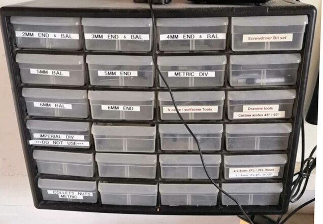
Most of them are made out of carbide steel or HSS. Wich is good for most of application. But for wood milling HSS tool work perfectly. And they are far less expensive than the carbide one. So it is preferable to brake HSS one than the carbide one. You can recognize the carbide one because there have black coated flute. ( We also have a Ti coated end mill gold looking)
Note : There is positive geometry and negative geometry tools. The positive one push the chip upwards, as the negative one push them downward.
Feeds & Speeds
Setting up the feedrate and the spindle speed can be a bit tricky and require lot of testing… So this is my advices to properly find the speeds and feeds of your equipments. For each material and each tools you have you will need a different speeds & feeds.
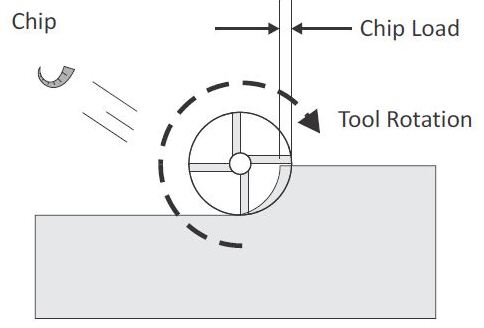
The speeds is the cutting speed of a tool’s tooth relative to the material surface. The feedrate is the linear speed of the tool trough the material. These to combinated move create a cut in the material. Eventually these move may create a chip. These to move create something called the chipload. Wich can be calculated like that :
Chipload
- : Feedrate (Linear speed of the tool in )
- RPM : Rotationnal speed of the spindle (in RPM)
- : Number of flute on your tool
This new parameter is very important. This provide all the theory you need to do some fine tuning of your milling machine. Depending of the chip load you will have a good surface quality or a tool break …
Here is the influence of the chipload :
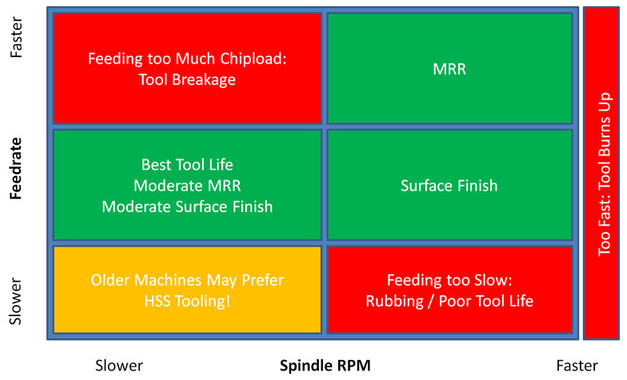
If the feedrate is too big relatively to the spindle RPM, the tool will not be able to cut material and will bump into it instead. The tool break or at least damage your material. On the other hand, if your spindle (Or router) spin too fast, the amount of material to cut will always be insufficient. Resulting in useless heating of both material and tool. Your tool with dull faster and your material surface will be burned. If you’re using Wax, plastic of even Aluminium, the material may melt and in case of aluminium, you’re tool may be stuck forever….
For each material, manufacturer provide recomended chipload. But the ideal chipload also depends on your tools, their conditions and on your machine. So manufacturer chipload are a good starting point. But you may have to adjust them by testing and according to your experience with CNC milling.
In our case we will start from the surface speed and with the chipload to find the spindle speeds and the feed rate.
There are the equations I’ve used :
Spindle speed :
- : Linear speed of a tool’s tooth in )
- N : Rotationnal speed of the spindle (in RPM)
- d : tool diameter
Feedrate :
- : Chipload in mm (mm / teeth)
- N : Rotationnal speed of the spindle (in RPM)
- Z : Number of teeth on your tool
Calculator
To facilitate the process of finding the right speeds and feeds. I’ve built a Google spreadsheet project.
Accessible here : Link to the file (Feel free to create a copy somewhere)
Using this file is simple. First of all the first top array contain the manufacturer’s chip load’s values according the the material you use and to the tool diameter. You should adjust those after testing. We’ll talk about testing further…
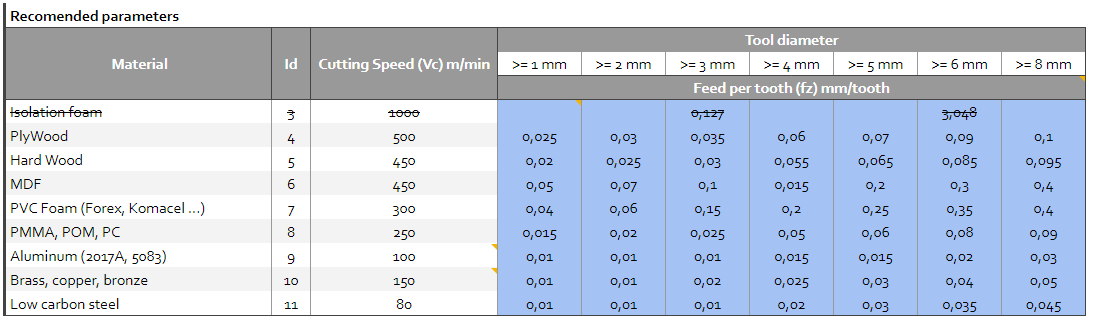
Be ware ! the chip load values ( ) aren’t 100% accurate. Don’t be too optimistic I may have done mistakes. But the value comes from our french tools manufacturer so I trust him !
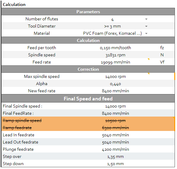
The second array is the calculation area. Just fill in the parameters area and use the Final feeds and speeds then.
You may also need some info. You can convert inches to mm and reverse. You can also put some reminder like the torque/speed data of your spindle.
Note : If you have a router (as at the Waag Fablab) you won’t be able to change the spindle speed during a cut. So You can ignore Ramping speed and feedrate. And use normal feedrate and spindle for these option.
A spindle can be controlled precisely over USB. But it is far more expensive. A router as to be set to the desired speed before the cut. You cannot change it during the cut.
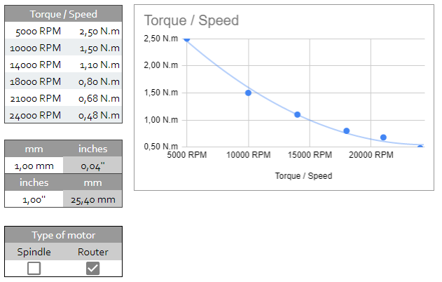
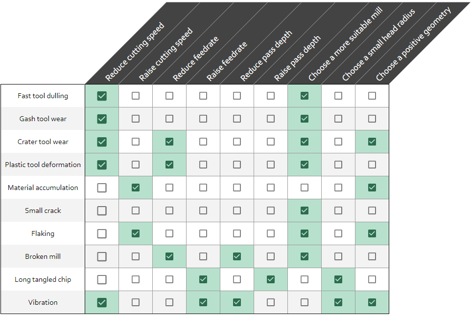
On the other tabs of the page you may find some useful diagnostic tools.
Like the following. This array allow you to check what happened and what to do.