Working with a CNC milling machine
Since my 3D printing samples on fabric are just laying around everywhere, I want to make a box for them. I will also include a lid so they won’t gather dust. This is about 2D (or 2,5D actually) milling. For my documentation on 3D milling, click here. Note: the Shopbot instructions are the same as the ones on this page.
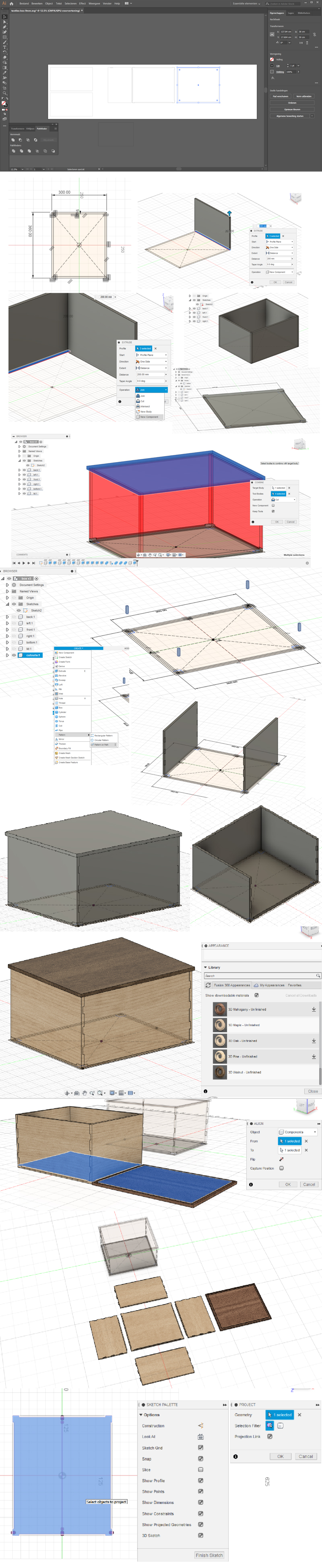
Step 1: modeling the box (Fusion360)
I first started to design this box in Illustrator, but I quickly realized that this required a lot of imagining what the box would look like. I switched to Fusion360 so I could actually see in 3D what I was doing. For this I followed this tutorial (this is part one of four). You can skip the third and fourth video if you don’t need any rendering and just need to the plans for the CNC machine.
To make a CAM layout I am using the align tool recommended in this tutorial. However exporting the file as a dxf gave me a lot of issues so after that I projected all parts onto separate sketches.
Tips:
- Create variables from the beginning. I did not do that but halway through modeling I started to regret that. Then you can let the software calculate all of your distances instead of having to do it yourself.
- Think about the paths you have to mill, VCarve Pro does not allow you to select separate paths so your vectors will have to be the path you want. I had to add extra outline paths because the paths I created in Fusion would have otherwise cut off my notches.
Step 2: create the toolpaths (VCarve Pro)
Notes
- Newer version of Partworks
- Design with Fusion360 (3d modeling software), Illustrator, Inkscape, Rhinoceros et cetera
- Export designed file(s) as eps, ai, stl, pdf, dxf
- Always measure the thickness of your material at different places before you start designing
- You can also draw directly on the canvas
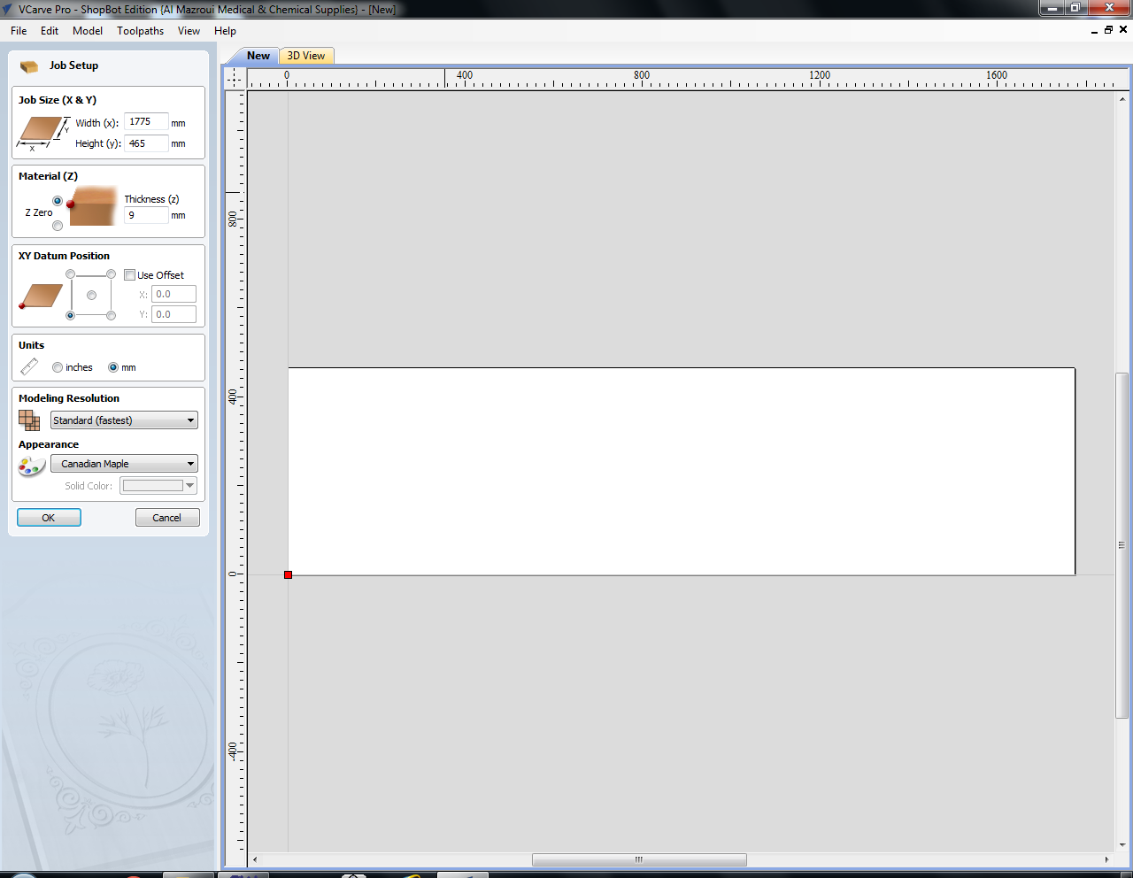
Job Setup: specify the size of the material (Job Size X & Y). The maximum size for this shopbot is 1,22m (Y) by 2,44m (X). Zero at the top of the material. Appearance and resolution only affect the rendering.
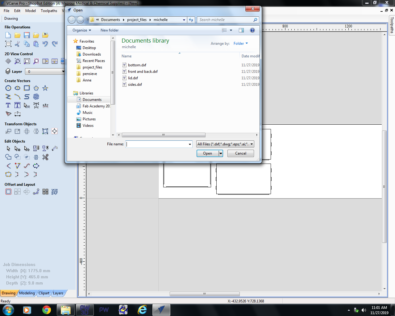
Import dxf files.
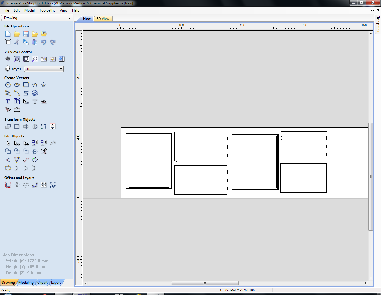
Determine the layout of the parts (wasting as little material as possible). You can also add small circles for the placement of the screws (mill these first as pockets). Then click the Toolpath menu on the right.
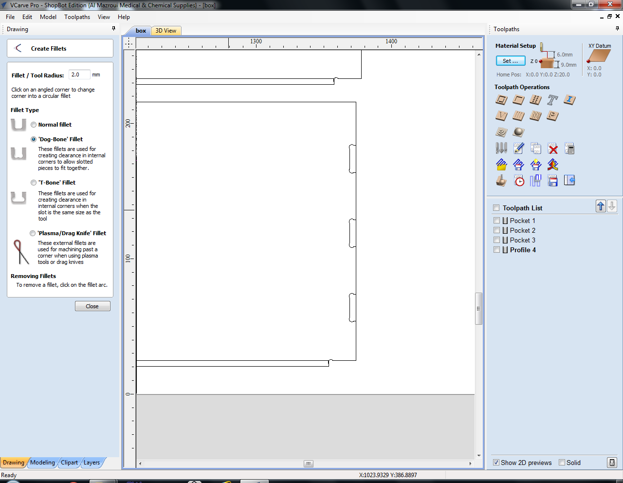
Add fillets if necessary. I used dogbone fillets to make sure my frased parts would fit together. You usually have to do this because of the restrictions a milling machine has: the milling bits are round, so sharp corners on the inside of a material are not possible.
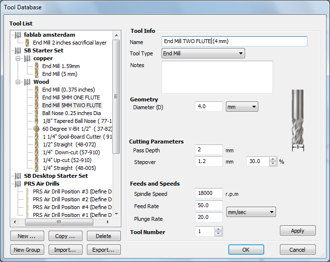
Select the mill you want to use from the tool database. I used a 4mm two flute endmill instead of the usual 5mm one as my notches were 4,5mm wide and a 5mm mill was too wide for thisx.
Flutes:
- One flute: fast straight lines (rough, for example for tests and prototypes or first runs)
- Two flute: more precise, for curves (standard)
- Four flute: even more precise (slowest, harder for the mill to get rid of the material that is being milled)
Settings:
- Tool type: end mill (flat) or ball nose mill (rounded)
- Diameter: diameter of the flute
- Pass depth: maximum depth of the material removed per pass (‘round’). For a two flute this
- Stepover: the distance between each pass of the machines tool head. The larger the stepover the faster the job will be machined, but the rougher the surface finish will be
- Spindle speed: rotations per minute of the mill. Maximum (and standard) is 18000 RPM. Changing this value here is only for your own information; you have to set this manually on the machine.
- Feed rate: speed of traveling through the material. For wood 50/60mm per second is a good start (with a two flute end mill); for foam this can be increased to 100/120mm per second (with a two flute end mill).
- Plunge rate: speed of traveling down into the material
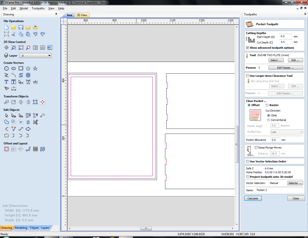
Create the pocket toolpaths before the cut-out toolpaths. The start depth (D) is the Z of the material, in my case this is 0mm but when you have pockets within pockets this can be more than 0. Cut depth (C) is the depth you want your pocket to have (relative to the start depth). For example: first pocket is 3mm deep, and the second pocket within this pocket is 2mm deep, then the start depth for the second pocket is 3mm and cut depth 2mm, a total of 5mm deep. Clear pocket in a raster or offset (see image). Raster works best with angular shapes, offset can be nice for rounded shapes but it depends on your design. Profile pass: last means that the machine mills the outer line last to get a smoother surface. When finished click calculate. You can preview the toolpath after that.
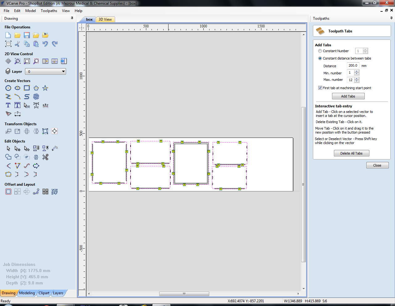
Create the cut-out toolpaths. Don’t forget to add tabs, these will make sure the material doesn’t start moving around once it’s almost cut out. You can start by filling in values and then click add tabs, but you can also use the mouse to add, remove and move tabs. Press calculate again and preview the toolpaths. If you are using one mill for everything you can export the toolpaths to a single file (an sbp file).
Step 3: Shopbot
Important:
- 18000 rotations per minute > DANGEROUS. Be extremely cautious with the placement of the bolts in the material because when you bump into metal with the mill it will generate sparks. In combination with sawdust there is the risk of fire or even explosion. Check everything you are doing constantly. A safety measure is to add the places for the bolt in the file and run those toolpaths first.
- NEVER LEAVE THE MACHINE
Before turning on the machine you have to prepare your material. Clean the bed, sand if necessary (otherwise it may not be level), align and screw the material to the underlying board (taking your file into account with the placement of the screws). When using foam, add double sided tape to the bottom of the material and stick it to the bed. Use two boards of wood to create a perpendicular angle, place the foam and use two more boards to surround the foam. This is because when it’s just taped the foam may come loose, ruining the whole model.
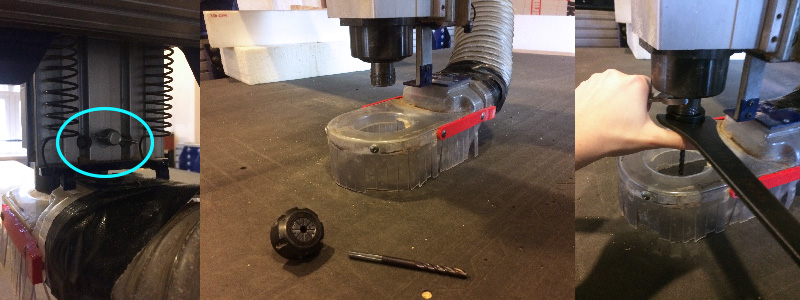
Lower the skirt by loosening the butterfly nut at the back of the machine head, Then grab the collet, nut and milling bit. First put the nut in the collet (you have to feel a click), then screw them in place using the wrench and plier. Then put in the milling bit and tighten everything very well and put the skirt back.
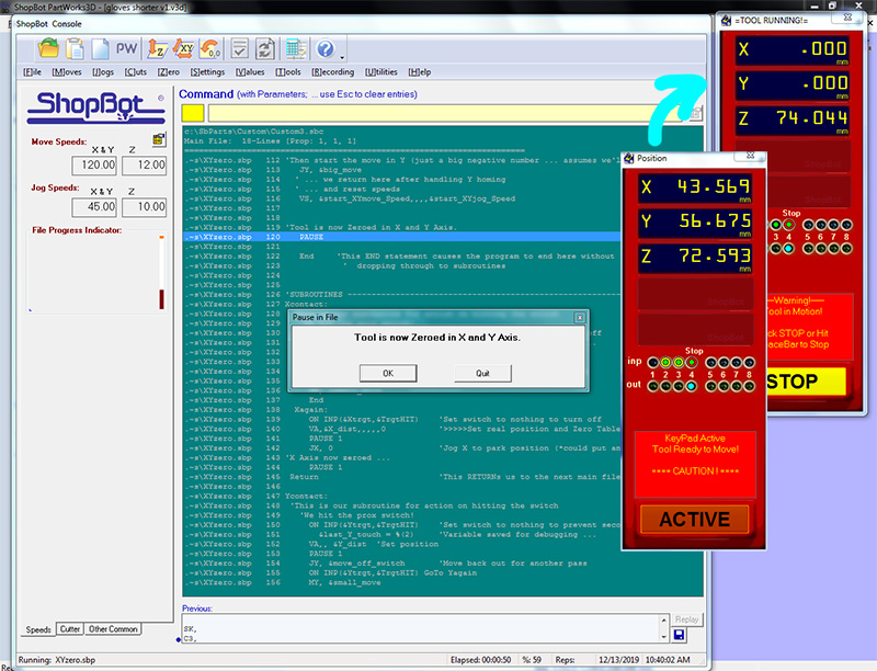
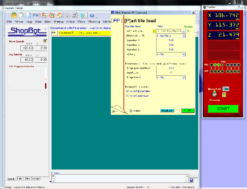
Open the Shopbot software before turning on the machine (otherwise there is no connection). After entering the keypad you can move the mill with the arrows in the keypad or the left arrow, right arrow, pgDown and pgUp.
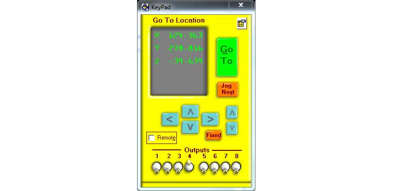
First you have to zero the X and Y axes. Move the machine to the preferred spot, take a screenshot of the X and Y position displayed in the menu and press 2. If for some reason the machine has to stop or the software crashes while milling, you can still continue with your file; otherwise the machine does not know where to start.
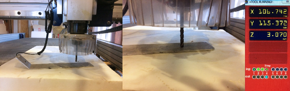
Before zeroing the Z axis, test if the milling bit and metal tool connect. If they do the light under output 1 lights up. Move the machine to the center of the material, put the metal tool under the mill and press the zero Z button. The machine will stop moving down as soon as it touches the metal. The tool is 3.070mm thick so that is where it will stop. Manually lift the mill with pgUp before you start moving the X and Y axes or you’ll destroy the machine/mill/tool.
Then load the partfile (don’t change anything in the file).
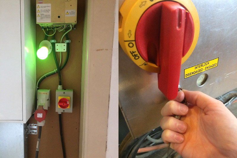
Turn on the power of the dust collector (switch in the back of the room, lamp turns green when it’s on), press the red button on the front of the machine to turn on the dust collector and use the knob to increase or decrease the power. Then turn on the spindle by turning the key in the keyhole.
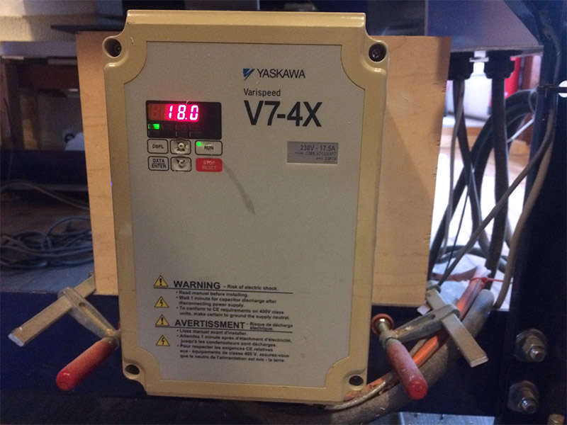
The spindle speed can be adjusted with the buttons on the box below the machine.
Keep your hand on the space bar for the first few minutes of milling to check if everything is going well.
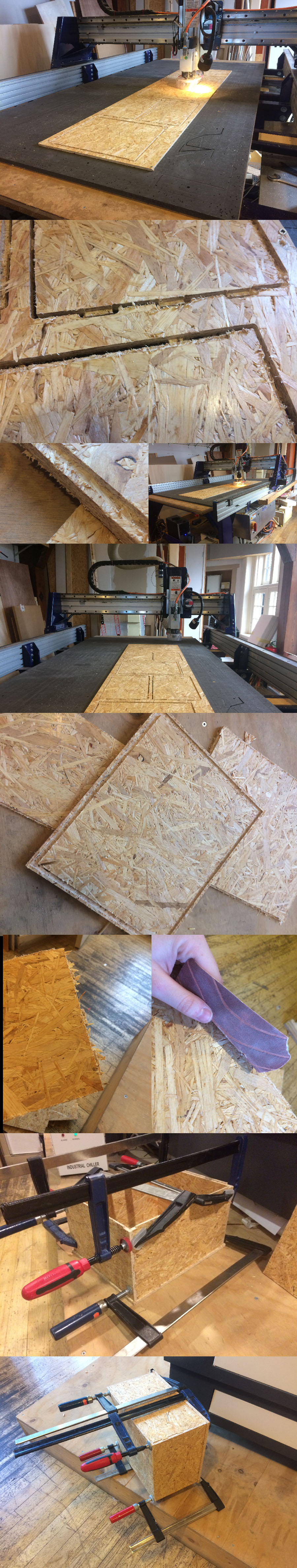
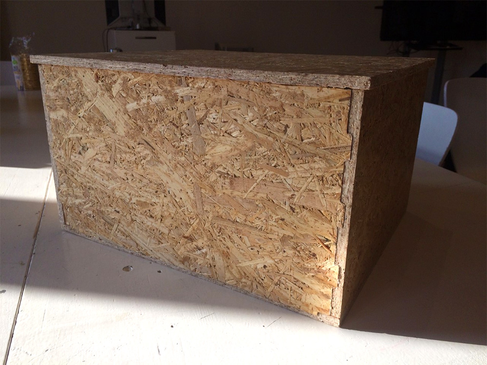
Final result
Links
Tutorial:
- Part 1: Modeling the box, bottom, and lid. Covers rabbets, grooves and miters.
- Part 2: Adding splines to reinforce the miters, modeling the thumb grip, and making the lid open and close using joints in Fusion.
- Part 3 : Applying wood materials, selecting the best grain, and photorealistic rendering.
- Part 4: Creating printable plans from the model.